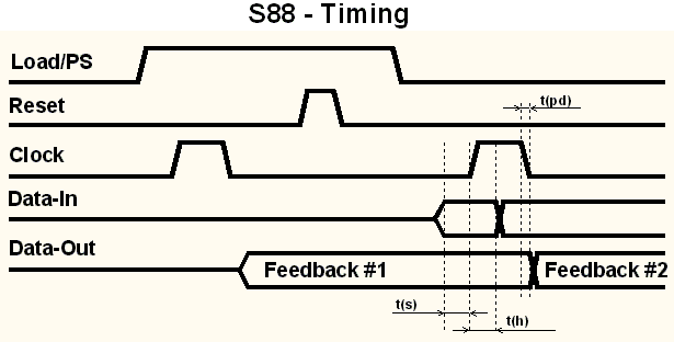
Timing of the s88-Bus
Current situation
Until now there no official specification for the s88 bus. In the following I try to define a reasonable value by looking at common used chips and wiring.
Analysis:
The original s88 feedback module comes with HEF4014 chips. These IC's have (at 5V) a tsetup up to 35ns and a thold up to 30ns. The propagation delay tpd amounts to 260ns.
The wiring introduces both propagation delay and capacitive loading. Typical cables have a tpd of 6,6ns/m, (resulting in approx. 200ns for 30ms maximum length). The capacitive load acts together with the output resistance as low pass filter. I.E. 44pF/m and a source resistance of 250 Ohms will give a trc of 11ns/m.
The timing of all known command stations (IB, HSI88, MC, 6050, etc.) is generated with slow bit banging, changing states after some 10µs. Some s88 module make use of this slow timing and implement the interface in software with a micro controller.
| Clockrates existing Interfaces | |||
|---|---|---|---|
| Command Station | t(high_min) | t(low_min) | Comment |
| Tams | 100µs | 100µs | low jitter, scan every 4.9ms |
| Littfinski HSI88 | 150µs | 150µs | low jitter |
| Intellibox | 30µs | 25µs | high jitter, average approx. 70µs |
| Nano-X-s88 | 50µs | 50µs | Jitter only in t-low |
| OpenDCC | 20µs | 20µs | Jitter, adjustable timing (via CV) |
| ECoS | 25µs | 25µs | unofficial value. ESU rejected to provide data and claimed 'IP right issues'. |
It looks like some implementations (the S88 bus is often implemented via a microcontroller) rely on this relaxed timing values. Depending on the vendor the appropriate routines vary in their speed. (Blücher seems to require at least 140µs cycle time, railway-lauf.de at least 200µs).
Sources for trouble:
- Mixing different S88 modules:
If fast devices are mixed with slow 4014 chips, a violation of t hold could occur. - impedeance mismatch:
s88 lines are *not really* terminated correctly, reflections and double clocking could occur.
Timing definitions

- At the input of a modul:
tsetup < 50ns, thold < 50ns, related to the rising edge. This slow timing allows for damping low passes on clock and data. - At the output of a module:
tpd > 1µs, to risk no t hold violation at the next module. Additionally tpd < 14µs (related to the negative clock edge) is required. This allows for a maximum read clock of 30kHz, which is more than sufficient. Changing output stage with the falling edge is strongly recommended. - Clock:
The slew rate should be limited to avoid reflections. trise > 300ns.
tcycle > 30µs and thigh> 15µs and tlow > 15µs; This should allow for micro controller implemented modules. The command station should have a configurable speed to interact with slower modules.